
Gencase: identical floatings have different number of particles

I created 3 identical cubes as floatings with this code:
<geometry>
...
  <commands>
   <mainlist>
    <setshapemode>dp|real|bound</setshapemode>
    <setdrawmodemode="full"/>

    <setmkboundmk="10"comment="reference,centredinframeorigin"/>
    <drawbox>
     <boxfill>solid</boxfill>
     <pointx="-0.5"y="-0.5"z="-0.5"/>
     <sizex="1"y="1"z="1"/>
    </drawbox>
    <shapeoutfile="10"reset="true"/>

    <setmkboundmk="30"comment=""/>
    <drawbox>
     <boxfill>solid</boxfill>
     <pointx="2.5"y="-0.5"z="1.5"/>
     <sizex="1"y="1"z="1"/>
    </drawbox>
    <shapeoutfile="30"reset="true"/>

    <setmkboundmk="31"comment=""/>
    <drawbox>
     <boxfill>solid</boxfill>
     <pointx="1.0"y="0.0"z="1.5"/>
     <sizex="1"y="1"z="1"/>
    </drawbox>
    <shapeoutfile="31"reset="true"/>
   </mainlist>
  </commands>
 </geometry>
 <floatings>
  <floatingmkbound="10"><massbodyvalue="1"/></floating>
  <floatingmkbound="30"><massbodyvalue="1"/></floating>
  <floatingmkbound="31"><massbodyvalue="1"/></floating>
 </floatings>
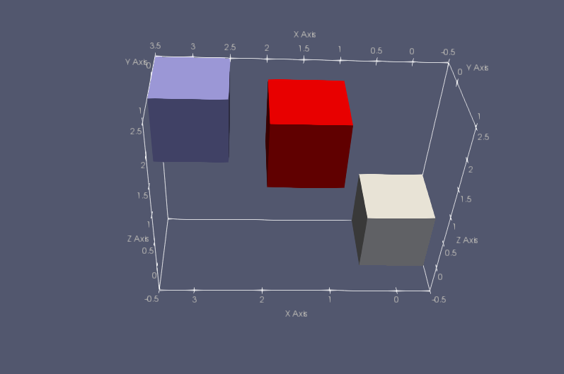
They look like this:
For dp=0.125 the properties of the first floating are
<floatingmkbound="10"mk="31"begin="0"count="1458">
<massbodyvalue="1"units_comment="kg"/>
<masspartvalue="0.000685871"units_comment="kg"/>
<centerx="0"y="0"z="0"units_comment="metres(m)"/>
<inertiax="0.208333"y="0.208333"z="0.208333"units_comment="kg*m^2"/>
</floating>
likewise for the others beside the centre of mass. Source: gencase xml output.
For dp=0.12 there are differences among the objects:
<floatingmkbound="10"mk="31"begin="0"count="1458">
<massbodyvalue="1"units_comment="kg"/>
<masspartvalue="0.000685871"units_comment="kg"/>
<centerx="-0.02"y="-0.02"z="-0.02"units_comment="metres(m)"/>
<inertiaunits_comment="kg*m^2">
<valuesv11="0.192"v12="2.16257e-17"v13="-9.51837e-19"/>
<valuesv21="2.16257e-17"v22="0.192"v23="2.28441e-19"/>
<valuesv31="-9.51837e-19"v32="2.28441e-19"v33="0.192"/>
--
<floatingmkbound="30"mk="51"begin="1458"count="1458">
<massbodyvalue="1"units_comment="kg"/>
<masspartvalue="0.000685871"units_comment="kg"/>
<centerx="2.98"y="-0.02"z="2.02"units_comment="metres(m)"/>
<inertiaunits_comment="kg*m^2">
<valuesv11="0.192"v12="-2.82505e-17"v13="7.99543e-19"/>
<valuesv21="-2.82505e-17"v22="0.192"v23="3.80735e-20"/>
<valuesv31="7.99543e-19"v32="3.80735e-20"v33="0.192"/>
--
<floatingmkbound="31"mk="52"begin="2916"count="1620">
<massbodyvalue="1"units_comment="kg"/>
<masspartvalue="0.000617284"units_comment="kg"/>
<centerx="1.54"y="0.52"z="2.02"units_comment="metres(m)"/>
<inertiaunits_comment="kg*m^2">
<valuesv11="0.2148"v12="1.00057e-17"v13="-1.13078e-18"/>
<valuesv21="1.00057e-17"v22="0.192"v23="-2.53569e-18"/>
<valuesv31="-1.13078e-18"v32="-2.53569e-18"v33="0.2148"/>
Do you spot mistakes/pitfalls? is anybody able to reproduce this? Tested with Gencase 4.0.092 and 4.0.109
Debug Trace
| Notice |
rich is deprecated. Use FormatService::renderHtml($content, Formats\RichFormat::FORMAT_KEY) instead.

#0 [internal function]: gdn_ErrorHandler(16384, 'rich is depreca...', '/var/www/forums...', 950, Array)
#1 /var/www/forums-dual-sphysics-org/library/core/functions.general.php(950): trigger_error('rich is depreca...', 16384)
#2 /var/www/forums-dual-sphysics-org/library/core/class.format.php(1729): deprecated('rich', 'FormatService::...')
#3 /var/www/forums-dual-sphysics-org/library/core/class.format.php(1479): Gdn_Format::rich('[{"insert":"I c...')
#4 /var/www/forums-dual-sphysics-org/applications/vanilla/controllers/class.discussioncontroller.php(197): Gdn_Format::to('[{"insert":"I c...', 'Rich')
#5 /var/www/forums-dual-sphysics-org/applications/vanilla/controllers/class.discussioncontroller.php(402): DiscussionController->index(1666, 'x', 'p1')
#6 /var/www/forums-dual-sphysics-org/library/core/class.dispatcher.php(862): DiscussionController->comment('3198')
#7 /var/www/forums-dual-sphysics-org/library/core/class.dispatcher.php(279): Gdn_Dispatcher->dispatchController(Object(Gdn_Request), Array)
#8 /var/www/forums-dual-sphysics-org/index.php(29): Gdn_Dispatcher->dispatch()
#9 {main} |
| Notice |
rich is deprecated. Use FormatService::renderHtml($content, Formats\RichFormat::FORMAT_KEY) instead.

#0 [internal function]: gdn_ErrorHandler(16384, 'rich is depreca...', '/var/www/forums...', 950, Array)
#1 /var/www/forums-dual-sphysics-org/library/core/functions.general.php(950): trigger_error('rich is depreca...', 16384)
#2 /var/www/forums-dual-sphysics-org/library/core/class.format.php(1729): deprecated('rich', 'FormatService::...')
#3 /var/www/forums-dual-sphysics-org/library/core/class.format.php(1479): Gdn_Format::rich('[{"insert":"I c...')
#4 /var/www/forums-dual-sphysics-org/applications/vanilla/views/discussion/helper_functions.php(24): Gdn_Format::to('[{"insert":"I c...', 'Rich')
#5 /var/www/forums-dual-sphysics-org/applications/vanilla/views/discussion/discussion.php(89): formatBody(Object(stdClass))
#6 /var/www/forums-dual-sphysics-org/applications/vanilla/views/discussion/index.php(31): include('/var/www/forums...')
#7 /var/www/forums-dual-sphysics-org/library/core/class.controller.php(778): include('/var/www/forums...')
#8 /var/www/forums-dual-sphysics-org/library/core/class.controller.php(1382): Gdn_Controller->fetchView('', false, false)
#9 /var/www/forums-dual-sphysics-org/library/core/class.pluggable.php(217): Gdn_Controller->xRender()
#10 /var/www/forums-dual-sphysics-org/applications/vanilla/controllers/class.discussioncontroller.php(310): Gdn_Pluggable->__call('render', Array)
#11 /var/www/forums-dual-sphysics-org/applications/vanilla/controllers/class.discussioncontroller.php(402): DiscussionController->index(1666, 'x', 'p1')
#12 /var/www/forums-dual-sphysics-org/library/core/class.dispatcher.php(862): DiscussionController->comment('3198')
#13 /var/www/forums-dual-sphysics-org/library/core/class.dispatcher.php(279): Gdn_Dispatcher->dispatchController(Object(Gdn_Request), Array)
#14 /var/www/forums-dual-sphysics-org/index.php(29): Gdn_Dispatcher->dispatch()
#15 {main} |
| Notice |
rich is deprecated. Use FormatService::renderHtml($content, Formats\RichFormat::FORMAT_KEY) instead.

#0 [internal function]: gdn_ErrorHandler(16384, 'rich is depreca...', '/var/www/forums...', 950, Array)
#1 /var/www/forums-dual-sphysics-org/library/core/functions.general.php(950): trigger_error('rich is depreca...', 16384)
#2 /var/www/forums-dual-sphysics-org/library/core/class.format.php(1729): deprecated('rich', 'FormatService::...')
#3 /var/www/forums-dual-sphysics-org/library/core/class.format.php(1479): Gdn_Format::rich('[{"insert":"Gen...')
#4 /var/www/forums-dual-sphysics-org/applications/vanilla/views/discussion/helper_functions.php(24): Gdn_Format::to('[{"insert":"Gen...', 'Rich')
#5 /var/www/forums-dual-sphysics-org/applications/vanilla/views/discussion/helper_functions.php(170): formatBody(Object(stdClass))
#6 /var/www/forums-dual-sphysics-org/applications/vanilla/views/discussion/comments.php(19): writeComment(Object(stdClass), Object(DiscussionController), Object(Gdn_Session), 1)
#7 /var/www/forums-dual-sphysics-org/applications/vanilla/views/discussion/index.php(53): include('/var/www/forums...')
#8 /var/www/forums-dual-sphysics-org/library/core/class.controller.php(778): include('/var/www/forums...')
#9 /var/www/forums-dual-sphysics-org/library/core/class.controller.php(1382): Gdn_Controller->fetchView('', false, false)
#10 /var/www/forums-dual-sphysics-org/library/core/class.pluggable.php(217): Gdn_Controller->xRender()
#11 /var/www/forums-dual-sphysics-org/applications/vanilla/controllers/class.discussioncontroller.php(310): Gdn_Pluggable->__call('render', Array)
#12 /var/www/forums-dual-sphysics-org/applications/vanilla/controllers/class.discussioncontroller.php(402): DiscussionController->index(1666, 'x', 'p1')
#13 /var/www/forums-dual-sphysics-org/library/core/class.dispatcher.php(862): DiscussionController->comment('3198')
#14 /var/www/forums-dual-sphysics-org/library/core/class.dispatcher.php(279): Gdn_Dispatcher->dispatchController(Object(Gdn_Request), Array)
#15 /var/www/forums-dual-sphysics-org/index.php(29): Gdn_Dispatcher->dispatch()
#16 {main} |
| Notice |
rich is deprecated. Use FormatService::renderHtml($content, Formats\RichFormat::FORMAT_KEY) instead.

#0 [internal function]: gdn_ErrorHandler(16384, 'rich is depreca...', '/var/www/forums...', 950, Array)
#1 /var/www/forums-dual-sphysics-org/library/core/functions.general.php(950): trigger_error('rich is depreca...', 16384)
#2 /var/www/forums-dual-sphysics-org/library/core/class.format.php(1729): deprecated('rich', 'FormatService::...')
#3 /var/www/forums-dual-sphysics-org/library/core/class.format.php(1479): Gdn_Format::rich('[{"insert":"And...')
#4 /var/www/forums-dual-sphysics-org/applications/vanilla/views/discussion/helper_functions.php(24): Gdn_Format::to('[{"insert":"And...', 'Rich')
#5 /var/www/forums-dual-sphysics-org/applications/vanilla/views/discussion/helper_functions.php(170): formatBody(Object(stdClass))
#6 /var/www/forums-dual-sphysics-org/applications/vanilla/views/discussion/comments.php(19): writeComment(Object(stdClass), Object(DiscussionController), Object(Gdn_Session), 2)
#7 /var/www/forums-dual-sphysics-org/applications/vanilla/views/discussion/index.php(53): include('/var/www/forums...')
#8 /var/www/forums-dual-sphysics-org/library/core/class.controller.php(778): include('/var/www/forums...')
#9 /var/www/forums-dual-sphysics-org/library/core/class.controller.php(1382): Gdn_Controller->fetchView('', false, false)
#10 /var/www/forums-dual-sphysics-org/library/core/class.pluggable.php(217): Gdn_Controller->xRender()
#11 /var/www/forums-dual-sphysics-org/applications/vanilla/controllers/class.discussioncontroller.php(310): Gdn_Pluggable->__call('render', Array)
#12 /var/www/forums-dual-sphysics-org/applications/vanilla/controllers/class.discussioncontroller.php(402): DiscussionController->index(1666, 'x', 'p1')
#13 /var/www/forums-dual-sphysics-org/library/core/class.dispatcher.php(862): DiscussionController->comment('3198')
#14 /var/www/forums-dual-sphysics-org/library/core/class.dispatcher.php(279): Gdn_Dispatcher->dispatchController(Object(Gdn_Request), Array)
#15 /var/www/forums-dual-sphysics-org/index.php(29): Gdn_Dispatcher->dispatch()
#16 {main} |
| Notice |
rich is deprecated. Use FormatService::renderHtml($content, Formats\RichFormat::FORMAT_KEY) instead.

#0 [internal function]: gdn_ErrorHandler(16384, 'rich is depreca...', '/var/www/forums...', 950, Array)
#1 /var/www/forums-dual-sphysics-org/library/core/functions.general.php(950): trigger_error('rich is depreca...', 16384)
#2 /var/www/forums-dual-sphysics-org/library/core/class.format.php(1729): deprecated('rich', 'FormatService::...')
#3 /var/www/forums-dual-sphysics-org/library/core/class.format.php(1479): Gdn_Format::rich('[{"insert":"Tha...')
#4 /var/www/forums-dual-sphysics-org/applications/vanilla/views/discussion/helper_functions.php(24): Gdn_Format::to('[{"insert":"Tha...', 'Rich')
#5 /var/www/forums-dual-sphysics-org/applications/vanilla/views/discussion/helper_functions.php(170): formatBody(Object(stdClass))
#6 /var/www/forums-dual-sphysics-org/applications/vanilla/views/discussion/comments.php(19): writeComment(Object(stdClass), Object(DiscussionController), Object(Gdn_Session), 3)
#7 /var/www/forums-dual-sphysics-org/applications/vanilla/views/discussion/index.php(53): include('/var/www/forums...')
#8 /var/www/forums-dual-sphysics-org/library/core/class.controller.php(778): include('/var/www/forums...')
#9 /var/www/forums-dual-sphysics-org/library/core/class.controller.php(1382): Gdn_Controller->fetchView('', false, false)
#10 /var/www/forums-dual-sphysics-org/library/core/class.pluggable.php(217): Gdn_Controller->xRender()
#11 /var/www/forums-dual-sphysics-org/applications/vanilla/controllers/class.discussioncontroller.php(310): Gdn_Pluggable->__call('render', Array)
#12 /var/www/forums-dual-sphysics-org/applications/vanilla/controllers/class.discussioncontroller.php(402): DiscussionController->index(1666, 'x', 'p1')
#13 /var/www/forums-dual-sphysics-org/library/core/class.dispatcher.php(862): DiscussionController->comment('3198')
#14 /var/www/forums-dual-sphysics-org/library/core/class.dispatcher.php(279): Gdn_Dispatcher->dispatchController(Object(Gdn_Request), Array)
#15 /var/www/forums-dual-sphysics-org/index.php(29): Gdn_Dispatcher->dispatch()
#16 {main} |
| Notice |
rich is deprecated. Use FormatService::renderHtml($content, Formats\RichFormat::FORMAT_KEY) instead.

#0 [internal function]: gdn_ErrorHandler(16384, 'rich is depreca...', '/var/www/forums...', 950, Array)
#1 /var/www/forums-dual-sphysics-org/library/core/functions.general.php(950): trigger_error('rich is depreca...', 16384)
#2 /var/www/forums-dual-sphysics-org/library/core/class.format.php(1729): deprecated('rich', 'FormatService::...')
#3 /var/www/forums-dual-sphysics-org/library/core/class.format.php(1479): Gdn_Format::rich('[{"insert":"(at...')
#4 /var/www/forums-dual-sphysics-org/applications/vanilla/views/discussion/helper_functions.php(24): Gdn_Format::to('[{"insert":"(at...', 'Rich')
#5 /var/www/forums-dual-sphysics-org/applications/vanilla/views/discussion/helper_functions.php(170): formatBody(Object(stdClass))
#6 /var/www/forums-dual-sphysics-org/applications/vanilla/views/discussion/comments.php(19): writeComment(Object(stdClass), Object(DiscussionController), Object(Gdn_Session), 4)
#7 /var/www/forums-dual-sphysics-org/applications/vanilla/views/discussion/index.php(53): include('/var/www/forums...')
#8 /var/www/forums-dual-sphysics-org/library/core/class.controller.php(778): include('/var/www/forums...')
#9 /var/www/forums-dual-sphysics-org/library/core/class.controller.php(1382): Gdn_Controller->fetchView('', false, false)
#10 /var/www/forums-dual-sphysics-org/library/core/class.pluggable.php(217): Gdn_Controller->xRender()
#11 /var/www/forums-dual-sphysics-org/applications/vanilla/controllers/class.discussioncontroller.php(310): Gdn_Pluggable->__call('render', Array)
#12 /var/www/forums-dual-sphysics-org/applications/vanilla/controllers/class.discussioncontroller.php(402): DiscussionController->index(1666, 'x', 'p1')
#13 /var/www/forums-dual-sphysics-org/library/core/class.dispatcher.php(862): DiscussionController->comment('3198')
#14 /var/www/forums-dual-sphysics-org/library/core/class.dispatcher.php(279): Gdn_Dispatcher->dispatchController(Object(Gdn_Request), Array)
#15 /var/www/forums-dual-sphysics-org/index.php(29): Gdn_Dispatcher->dispatch()
#16 {main} |
| Notice |
rich is deprecated. Use FormatService::renderHtml($content, Formats\RichFormat::FORMAT_KEY) instead.

#0 [internal function]: gdn_ErrorHandler(16384, 'rich is depreca...', '/var/www/forums...', 950, Array)
#1 /var/www/forums-dual-sphysics-org/library/core/functions.general.php(950): trigger_error('rich is depreca...', 16384)
#2 /var/www/forums-dual-sphysics-org/library/core/class.format.php(1729): deprecated('rich', 'FormatService::...')
#3 /var/www/forums-dual-sphysics-org/library/core/class.format.php(1479): Gdn_Format::rich('[{"insert":"I k...')
#4 /var/www/forums-dual-sphysics-org/applications/vanilla/views/discussion/helper_functions.php(24): Gdn_Format::to('[{"insert":"I k...', 'Rich')
#5 /var/www/forums-dual-sphysics-org/applications/vanilla/views/discussion/helper_functions.php(170): formatBody(Object(stdClass))
#6 /var/www/forums-dual-sphysics-org/applications/vanilla/views/discussion/comments.php(19): writeComment(Object(stdClass), Object(DiscussionController), Object(Gdn_Session), 5)
#7 /var/www/forums-dual-sphysics-org/applications/vanilla/views/discussion/index.php(53): include('/var/www/forums...')
#8 /var/www/forums-dual-sphysics-org/library/core/class.controller.php(778): include('/var/www/forums...')
#9 /var/www/forums-dual-sphysics-org/library/core/class.controller.php(1382): Gdn_Controller->fetchView('', false, false)
#10 /var/www/forums-dual-sphysics-org/library/core/class.pluggable.php(217): Gdn_Controller->xRender()
#11 /var/www/forums-dual-sphysics-org/applications/vanilla/controllers/class.discussioncontroller.php(310): Gdn_Pluggable->__call('render', Array)
#12 /var/www/forums-dual-sphysics-org/applications/vanilla/controllers/class.discussioncontroller.php(402): DiscussionController->index(1666, 'x', 'p1')
#13 /var/www/forums-dual-sphysics-org/library/core/class.dispatcher.php(862): DiscussionController->comment('3198')
#14 /var/www/forums-dual-sphysics-org/library/core/class.dispatcher.php(279): Gdn_Dispatcher->dispatchController(Object(Gdn_Request), Array)
#15 /var/www/forums-dual-sphysics-org/index.php(29): Gdn_Dispatcher->dispatch()
#16 {main} |
| Notice |
rich is deprecated. Use FormatService::renderHtml($content, Formats\RichFormat::FORMAT_KEY) instead.

#0 [internal function]: gdn_ErrorHandler(16384, 'rich is depreca...', '/var/www/forums...', 950, Array)
#1 /var/www/forums-dual-sphysics-org/library/core/functions.general.php(950): trigger_error('rich is depreca...', 16384)
#2 /var/www/forums-dual-sphysics-org/library/core/class.format.php(1729): deprecated('rich', 'FormatService::...')
#3 /var/www/forums-dual-sphysics-org/library/core/class.format.php(1479): Gdn_Format::rich('[{"insert":"Tes...')
#4 /var/www/forums-dual-sphysics-org/applications/vanilla/views/discussion/helper_functions.php(24): Gdn_Format::to('[{"insert":"Tes...', 'Rich')
#5 /var/www/forums-dual-sphysics-org/applications/vanilla/views/discussion/helper_functions.php(170): formatBody(Object(stdClass))
#6 /var/www/forums-dual-sphysics-org/applications/vanilla/views/discussion/comments.php(19): writeComment(Object(stdClass), Object(DiscussionController), Object(Gdn_Session), 6)
#7 /var/www/forums-dual-sphysics-org/applications/vanilla/views/discussion/index.php(53): include('/var/www/forums...')
#8 /var/www/forums-dual-sphysics-org/library/core/class.controller.php(778): include('/var/www/forums...')
#9 /var/www/forums-dual-sphysics-org/library/core/class.controller.php(1382): Gdn_Controller->fetchView('', false, false)
#10 /var/www/forums-dual-sphysics-org/library/core/class.pluggable.php(217): Gdn_Controller->xRender()
#11 /var/www/forums-dual-sphysics-org/applications/vanilla/controllers/class.discussioncontroller.php(310): Gdn_Pluggable->__call('render', Array)
#12 /var/www/forums-dual-sphysics-org/applications/vanilla/controllers/class.discussioncontroller.php(402): DiscussionController->index(1666, 'x', 'p1')
#13 /var/www/forums-dual-sphysics-org/library/core/class.dispatcher.php(862): DiscussionController->comment('3198')
#14 /var/www/forums-dual-sphysics-org/library/core/class.dispatcher.php(279): Gdn_Dispatcher->dispatchController(Object(Gdn_Request), Array)
#15 /var/www/forums-dual-sphysics-org/index.php(29): Gdn_Dispatcher->dispatch()
#16 {main} |
| Notice |
rich is deprecated. Use FormatService::renderHtml($content, Formats\RichFormat::FORMAT_KEY) instead.

#0 [internal function]: gdn_ErrorHandler(16384, 'rich is depreca...', '/var/www/forums...', 950, Array)
#1 /var/www/forums-dual-sphysics-org/library/core/functions.general.php(950): trigger_error('rich is depreca...', 16384)
#2 /var/www/forums-dual-sphysics-org/library/core/class.format.php(1729): deprecated('rich', 'FormatService::...')
#3 /var/www/forums-dual-sphysics-org/library/core/class.format.php(1479): Gdn_Format::rich('[{"insert":"The...')
#4 /var/www/forums-dual-sphysics-org/applications/vanilla/views/discussion/helper_functions.php(24): Gdn_Format::to('[{"insert":"The...', 'Rich')
#5 /var/www/forums-dual-sphysics-org/applications/vanilla/views/discussion/helper_functions.php(170): formatBody(Object(stdClass))
#6 /var/www/forums-dual-sphysics-org/applications/vanilla/views/discussion/comments.php(19): writeComment(Object(stdClass), Object(DiscussionController), Object(Gdn_Session), 7)
#7 /var/www/forums-dual-sphysics-org/applications/vanilla/views/discussion/index.php(53): include('/var/www/forums...')
#8 /var/www/forums-dual-sphysics-org/library/core/class.controller.php(778): include('/var/www/forums...')
#9 /var/www/forums-dual-sphysics-org/library/core/class.controller.php(1382): Gdn_Controller->fetchView('', false, false)
#10 /var/www/forums-dual-sphysics-org/library/core/class.pluggable.php(217): Gdn_Controller->xRender()
#11 /var/www/forums-dual-sphysics-org/applications/vanilla/controllers/class.discussioncontroller.php(310): Gdn_Pluggable->__call('render', Array)
#12 /var/www/forums-dual-sphysics-org/applications/vanilla/controllers/class.discussioncontroller.php(402): DiscussionController->index(1666, 'x', 'p1')
#13 /var/www/forums-dual-sphysics-org/library/core/class.dispatcher.php(862): DiscussionController->comment('3198')
#14 /var/www/forums-dual-sphysics-org/library/core/class.dispatcher.php(279): Gdn_Dispatcher->dispatchController(Object(Gdn_Request), Array)
#15 /var/www/forums-dual-sphysics-org/index.php(29): Gdn_Dispatcher->dispatch()
#16 {main} |
Comments
GenCase creates an initial lattice with size of dp.... Therefore the initial and final particle in one of the dimensions of your boxes will depend on that lattice size...
The boxes should be created with global dimensions of 1x1x1 however they will then converted in terms of "dp", perhaps for the third box extra layer of particles are created.... when using value of 0.12 instead of 0.15
You can visualise the positions of the particles at edges in paraview to understand if extra layer of particles are created when modifying "dp"
Regards
And to continue on Alex's explanation, this is also why it is extremely important, when working with floatings and you want an exact weight, to specify the weight directly! That way no matter if you have 50 or 60 particles it will have the weight you expect, instead of being some approximated number.
But I really like what you are doing by testing a lot of use cases of GenCase out, maybe stuff like this could be useful for new and experienced users on the Github wiki etc.
Kind regards
Thanks for all feedback. If I may take your comments as a confirmation that there is no formal error in my coding, then I would rise the level of concern. I agree that the assigned mass is conserved since particle count times particle mass matches the desired value. However please notice the following points
Would you mind it terribly to reproduce these results for my peace of mind?
(As an aside please feel free to reuse all the material that I publish in this forum as you like. I do not have enough spare time to contribute to the wiki directly, but I certainly would if I could.)
(attempt to save jottings as draft comment failed)
I kept on playing around with GenCase and the three cubes above. They have edge lenght L= 1m, mass M=1 kg and theoretical isotropic moment of inertia of I=1.667 kgm². The white cube shown in the sketch in the post above is centred in the origin of the reference frame and is Cube #1. The blue cube is Cube #2, the red is Cube #3.
I have considered two design situations separately.
In the first one, the particle spacing dp is such that L/dp is an integer. Each edge will contain exactly L/dp+1 particles and the cube 2*(L/dp + 1)³ particles neatly placed within the intended cube shape. (The factor 2 depends on modelling choices discussed elsewhere.) Here I consider a range 8-96 sufficient to cover many situations of practical interest.
In the second one, thirty particle spacings are picked randomly so as to sample a uniform distribution of L/dp in the same interval 8-96. This represents the likely situation where a user chooses dp without a focus on floating objects.
The results of these GenCase launches are in this plot:
Integer L/dp
For integer L/dp's the inertia tensors of all cubes are isotropic. The numerical moment of inertia computed by DualSPHysics converges to the exact value linearly in Dp (not shown). This can be expected . The convergence of the computed isotropic moment of inertia is shown by the gray curve.
Note that, for the numerical moments are greater than the exact one, a floating object in DualSPHysics will always behave more sluggishly than assigned: expect thus less angular acceleration for given torques, or a greater torque to obtain a given angular acceleration. Perhaps this is a wiki-worthy tip, useful to interpret progress and published results?
Arbitrary L/dp
For arbitrary L/dp's the situation is unexpectedly puzzling. Two forms of irregularity are evident: differences between cubes and anisotropy.
Concerning consistency, I colour-coded the cubes with the same colours as in the earlier sketch, expect for swapping white with black.
Concerning anisotropy, the moments of inertia in x, y and z direction of a single cube are symbolized by a butterfly and downward or upward pointing triangles. These symbols overlap to a square when the inertia tensor is isotropic as expected. Symbols others than a square, conversely, indicate unexpected anisotropy. I also checked that the inertia products are zero as expected.
The evidence gathered this way is that, with arbitrary L/dp, cube #1 is always isotropic but off the values obtained with integer L/dp's. Cube #1 and #2 are often anisotropic and quite often differ from each other. These irregularities are within about +/- 3% of the expected numerical values. Please note that symbols are not transparent, so colours may mask one another.
Discussion
Unless I unintentionally succeeded in making a house of cards out of it, the difference between the three cubes is just as unexpected as a for-loop that does not repeat the same instruction. I am still pretty puzzled by it; I cannot figure out any rationale to retrieve both isotropy and anisotropy from the identical cubes. Could it then be that fixing this loop issue also eliminates the lack of isotropy?
Secondly, departures of isotropic moments from the grey curve could be expected for non-integer L/dp's. If L/dp is an arbitrary number, the number of particles for discretizing a floating object has to be rounded up/down to an integer, say from 8.3333 to 8. So there can exist floating objects having the same number of particles but particles differently spaced because of the chosen dp. This will lead to a slightly different distribution of masses around the centre of mass, hence a different moment of inertia. However, this approximation should come with a bit of regularity that is not observable at this moment.
Conclusions
To derive these data sets I have consistently used the bash script attached, for anyone to double check, duplicate and verify. This launches a GenCase run, parses the resulting xml file and picks the inertia tensor values. I am grateful to anyone who points out glitches and faults. If this information is proven sound and reproducible, I hope it raises points for attentions worth triaging. Where applicable, a patch would be useful.
Minor presentational feature request
When L/dp is a power of 2, the output is:
else it is
For generality, ease of scripting and control it would be ideal to show the full tensor throughout and to use a uniform number notation (say scientific).
Thanks for your reading and considering.
Testing conservation of angular momentum
I have chosen a particle spacing that appears to give anisotropic moments of inertia from the plot above (L/dp~23) and applied a initial angular velocity of (0,0,20pi). I have turned off gravity and there is no fluid. I have run a simulation of 0.06 seconds with data output each 0.01 s. For the time marching I have given a conventional sound speed of 10 m/s and let DualSPHysics go. The average time step is of the order 0.0001 s.
The expectation is that the cubes rotate indefinitely because of conservation of angular momentum in the absence of external forces, in the vacuum effectively. With the angular velocity assigned this means that the cubes should sweep 36 degrees between two rounds of output.
I have used "DualSPHysics4 [Symmetry] v4.4.010 (21-06-2019)", "FloatingInfo4 v4.0.030 (21-06-2019)" and "GenCase4 v4.0.109 (21-06-2019)".
Below I also attached the xml output of GenCase (input for DualSPHysics), the bash script used to drive the computing 'inertiarotation.sh', and the output of DualSPHysics 'Run.out'.
Tabulation
The table below summarises the information on the objects given by FloatingInfo. Mkbound10 is the white cube, mkbound30 the blue one, mkbound31 the red one. The columns A through Q contain the output of FloatingInfo, with some cells hidden.
Columns S through U are side calculations and show the angular speeds based on the roll, pitch and yaw angles in columns O-Q; they should be equal to the angular velocities in columns F-H.
The orange cells are the moments of inertia computed by GenCase. Mkbound10 is isotropic, mkbound20 and mkbound21 have has one moment of inertia differing from the other two, mkbound30 has three different moments of inertia.
First question
In column H I recognize the angular velocity of 62 rad/sec that I assigned. However, in column Q the yaw angles swept by all cubes during the first 0.01 seconds are less than 36 degrees. These cells are marked in yellow. Afterwards the yaw angles are 36 degrees within some approximation; see column U for the attending speeds.
If we look at the snapshots of the cubes at time 0, 0.01 and 0.02 we can see that this is not an artefact of FloatingInfo. The angle swept during the first 0.01 s is clearly not 36 degrees. Any clue why this happens?
Second question
The purple cell shows that one yaw angle takes suddenly a negative value of -170 degrees. Taking into account the error of the yellow cell I would have expected a value around 190 degrees there. Here, though, I realise that 190=360-170. So we are talking about the same angle.
The roll and pitch angles in column O-P are expected to be zero or just around it. The red cells show that they start to oscillate around somewhere close to -180 degrees instead. This is not the same angle, I think.
These results may well be a presentational artefact of FloatingInfo. What are the definition and criteria used to compute the roll, pitch and yaw angles? This would help interpret and process the results.
Conclusion
Please do not hesitate to verify and point out limitations in this test. If confirmed, a patch would be welcome. If confuted, suggestions are welcome.
The topic of moments of inertia is moved to https://github.com/DualSPHysics/DualSPHysics/issues/72
The topic of angular momentum is moved to and superseded by issue https://github.com/DualSPHysics/DualSPHysics/issues/74