
Issue with DRAWROTATE

Dear,
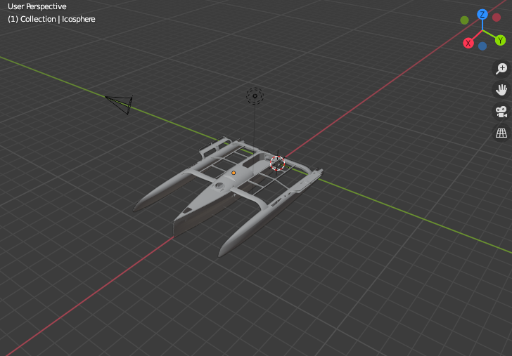
I just came not to understand the way drawrotate works. The first example states the problem.
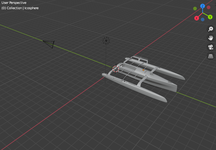
When I prescribe a rotation around the Z axis (second example), the X and Y axis seem to swap.
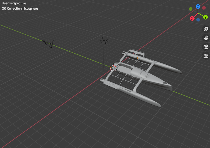
As a result, when I add a rotation around the X axis, the model does rotate, but around the Y axis (third example).
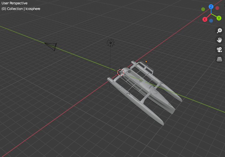
If I add a rotation around the Y axis, the model does rotate, but around the X-axis (fourth example), in inverse trigonometric direction.
As a result, I am not so sure where to put the Center of Gravity of the floatings...
Do someone has the same issue ?
<geometry>
<drawfilestl file="TF10_Assembly.stl">
<drawscale x="0.001" y="0.001" z="0.001" />
<drawmove x="0" y="0.0" z="0.0" />
<drawrotate angx="0" angy="0.0" angz="0.0" />
<floatings>
<floating mkbound="20">
<massbody value="1633" />
<center x="4.604" y="0.00" z="1.426" />
<geometry>
<drawfilestl file="TF10_Assembly.stl">
<drawscale x="0.001" y="0.001" z="0.001" />
<drawmove x="0" y="0.0" z="0.0" />
<drawrotate angx="0" angy="0.0" angz="90.0" />
<floatings>
<floating mkbound="20">
<massbody value="1633" />
<center x="0.0" y="4.604" z="1.426" />
<geometry>
<drawfilestl file="TF10_Assembly.stl">
<drawscale x="0.001" y="0.001" z="0.001" />
<drawmove x="0" y="0.0" z="0.0" />
<drawrotate angx="20.0" angy="0.0" angz="90.0" />
<floatings>
<floating mkbound="20">
<massbody value="1633" />
<center x="0.0" y="3.8386" z="2.9146" />
<geometry>
<drawfilestl file="TF10_Assembly.stl">
<drawscale x="0.001" y="0.001" z="0.001" />
<drawmove x="0" y="0.0" z="0.0" />
<drawrotate angx="0.0" angy="20.0" angz="90.0" />
<floatings>
<floating mkbound="20">
<massbody value="1633" />
<center x="0.0" y="3.8386" z="2.9146" />
Debug Trace
| Notice |
rich is deprecated. Use FormatService::renderHtml($content, Formats\RichFormat::FORMAT_KEY) instead.

#0 [internal function]: gdn_ErrorHandler(16384, 'rich is depreca...', '/var/www/forums...', 950, Array)
#1 /var/www/forums-dual-sphysics-org/library/core/functions.general.php(950): trigger_error('rich is depreca...', 16384)
#2 /var/www/forums-dual-sphysics-org/library/core/class.format.php(1729): deprecated('rich', 'FormatService::...')
#3 /var/www/forums-dual-sphysics-org/library/core/class.format.php(1479): Gdn_Format::rich('[{"insert":"Dea...')
#4 /var/www/forums-dual-sphysics-org/applications/vanilla/controllers/class.discussioncontroller.php(197): Gdn_Format::to('[{"insert":"Dea...', 'Rich')
#5 /var/www/forums-dual-sphysics-org/applications/vanilla/controllers/class.discussioncontroller.php(402): DiscussionController->index(2336, 'x', 'p1')
#6 /var/www/forums-dual-sphysics-org/library/core/class.dispatcher.php(862): DiscussionController->comment('5213')
#7 /var/www/forums-dual-sphysics-org/library/core/class.dispatcher.php(279): Gdn_Dispatcher->dispatchController(Object(Gdn_Request), Array)
#8 /var/www/forums-dual-sphysics-org/index.php(29): Gdn_Dispatcher->dispatch()
#9 {main} |
| Notice |
rich is deprecated. Use FormatService::renderHtml($content, Formats\RichFormat::FORMAT_KEY) instead.

#0 [internal function]: gdn_ErrorHandler(16384, 'rich is depreca...', '/var/www/forums...', 950, Array)
#1 /var/www/forums-dual-sphysics-org/library/core/functions.general.php(950): trigger_error('rich is depreca...', 16384)
#2 /var/www/forums-dual-sphysics-org/library/core/class.format.php(1729): deprecated('rich', 'FormatService::...')
#3 /var/www/forums-dual-sphysics-org/library/core/class.format.php(1479): Gdn_Format::rich('[{"insert":"Dea...')
#4 /var/www/forums-dual-sphysics-org/applications/vanilla/views/discussion/helper_functions.php(24): Gdn_Format::to('[{"insert":"Dea...', 'Rich')
#5 /var/www/forums-dual-sphysics-org/applications/vanilla/views/discussion/discussion.php(89): formatBody(Object(stdClass))
#6 /var/www/forums-dual-sphysics-org/applications/vanilla/views/discussion/index.php(31): include('/var/www/forums...')
#7 /var/www/forums-dual-sphysics-org/library/core/class.controller.php(778): include('/var/www/forums...')
#8 /var/www/forums-dual-sphysics-org/library/core/class.controller.php(1382): Gdn_Controller->fetchView('', false, false)
#9 /var/www/forums-dual-sphysics-org/library/core/class.pluggable.php(217): Gdn_Controller->xRender()
#10 /var/www/forums-dual-sphysics-org/applications/vanilla/controllers/class.discussioncontroller.php(310): Gdn_Pluggable->__call('render', Array)
#11 /var/www/forums-dual-sphysics-org/applications/vanilla/controllers/class.discussioncontroller.php(402): DiscussionController->index(2336, 'x', 'p1')
#12 /var/www/forums-dual-sphysics-org/library/core/class.dispatcher.php(862): DiscussionController->comment('5213')
#13 /var/www/forums-dual-sphysics-org/library/core/class.dispatcher.php(279): Gdn_Dispatcher->dispatchController(Object(Gdn_Request), Array)
#14 /var/www/forums-dual-sphysics-org/index.php(29): Gdn_Dispatcher->dispatch()
#15 {main} |
| Notice |
rich is deprecated. Use FormatService::renderHtml($content, Formats\RichFormat::FORMAT_KEY) instead.

#0 [internal function]: gdn_ErrorHandler(16384, 'rich is depreca...', '/var/www/forums...', 950, Array)
#1 /var/www/forums-dual-sphysics-org/library/core/functions.general.php(950): trigger_error('rich is depreca...', 16384)
#2 /var/www/forums-dual-sphysics-org/library/core/class.format.php(1729): deprecated('rich', 'FormatService::...')
#3 /var/www/forums-dual-sphysics-org/library/core/class.format.php(1479): Gdn_Format::rich('[{"insert":"Hel...')
#4 /var/www/forums-dual-sphysics-org/applications/vanilla/views/discussion/helper_functions.php(24): Gdn_Format::to('[{"insert":"Hel...', 'Rich')
#5 /var/www/forums-dual-sphysics-org/applications/vanilla/views/discussion/helper_functions.php(170): formatBody(Object(stdClass))
#6 /var/www/forums-dual-sphysics-org/applications/vanilla/views/discussion/comments.php(19): writeComment(Object(stdClass), Object(DiscussionController), Object(Gdn_Session), 1)
#7 /var/www/forums-dual-sphysics-org/applications/vanilla/views/discussion/index.php(53): include('/var/www/forums...')
#8 /var/www/forums-dual-sphysics-org/library/core/class.controller.php(778): include('/var/www/forums...')
#9 /var/www/forums-dual-sphysics-org/library/core/class.controller.php(1382): Gdn_Controller->fetchView('', false, false)
#10 /var/www/forums-dual-sphysics-org/library/core/class.pluggable.php(217): Gdn_Controller->xRender()
#11 /var/www/forums-dual-sphysics-org/applications/vanilla/controllers/class.discussioncontroller.php(310): Gdn_Pluggable->__call('render', Array)
#12 /var/www/forums-dual-sphysics-org/applications/vanilla/controllers/class.discussioncontroller.php(402): DiscussionController->index(2336, 'x', 'p1')
#13 /var/www/forums-dual-sphysics-org/library/core/class.dispatcher.php(862): DiscussionController->comment('5213')
#14 /var/www/forums-dual-sphysics-org/library/core/class.dispatcher.php(279): Gdn_Dispatcher->dispatchController(Object(Gdn_Request), Array)
#15 /var/www/forums-dual-sphysics-org/index.php(29): Gdn_Dispatcher->dispatch()
#16 {main} |
| Notice |
rich is deprecated. Use FormatService::renderHtml($content, Formats\RichFormat::FORMAT_KEY) instead.

#0 [internal function]: gdn_ErrorHandler(16384, 'rich is depreca...', '/var/www/forums...', 950, Array)
#1 /var/www/forums-dual-sphysics-org/library/core/functions.general.php(950): trigger_error('rich is depreca...', 16384)
#2 /var/www/forums-dual-sphysics-org/library/core/class.format.php(1729): deprecated('rich', 'FormatService::...')
#3 /var/www/forums-dual-sphysics-org/library/core/class.format.php(1479): Gdn_Format::rich('[{"insert":"Dea...')
#4 /var/www/forums-dual-sphysics-org/applications/vanilla/views/discussion/helper_functions.php(24): Gdn_Format::to('[{"insert":"Dea...', 'Rich')
#5 /var/www/forums-dual-sphysics-org/applications/vanilla/views/discussion/helper_functions.php(170): formatBody(Object(stdClass))
#6 /var/www/forums-dual-sphysics-org/applications/vanilla/views/discussion/comments.php(19): writeComment(Object(stdClass), Object(DiscussionController), Object(Gdn_Session), 2)
#7 /var/www/forums-dual-sphysics-org/applications/vanilla/views/discussion/index.php(53): include('/var/www/forums...')
#8 /var/www/forums-dual-sphysics-org/library/core/class.controller.php(778): include('/var/www/forums...')
#9 /var/www/forums-dual-sphysics-org/library/core/class.controller.php(1382): Gdn_Controller->fetchView('', false, false)
#10 /var/www/forums-dual-sphysics-org/library/core/class.pluggable.php(217): Gdn_Controller->xRender()
#11 /var/www/forums-dual-sphysics-org/applications/vanilla/controllers/class.discussioncontroller.php(310): Gdn_Pluggable->__call('render', Array)
#12 /var/www/forums-dual-sphysics-org/applications/vanilla/controllers/class.discussioncontroller.php(402): DiscussionController->index(2336, 'x', 'p1')
#13 /var/www/forums-dual-sphysics-org/library/core/class.dispatcher.php(862): DiscussionController->comment('5213')
#14 /var/www/forums-dual-sphysics-org/library/core/class.dispatcher.php(279): Gdn_Dispatcher->dispatchController(Object(Gdn_Request), Array)
#15 /var/www/forums-dual-sphysics-org/index.php(29): Gdn_Dispatcher->dispatch()
#16 {main} |
| Notice |
rich is deprecated. Use FormatService::renderHtml($content, Formats\RichFormat::FORMAT_KEY) instead.

#0 [internal function]: gdn_ErrorHandler(16384, 'rich is depreca...', '/var/www/forums...', 950, Array)
#1 /var/www/forums-dual-sphysics-org/library/core/functions.general.php(950): trigger_error('rich is depreca...', 16384)
#2 /var/www/forums-dual-sphysics-org/library/core/class.format.php(1729): deprecated('rich', 'FormatService::...')
#3 /var/www/forums-dual-sphysics-org/library/core/class.format.php(1479): Gdn_Format::rich('[{"insert":"Ple...')
#4 /var/www/forums-dual-sphysics-org/applications/vanilla/views/discussion/helper_functions.php(24): Gdn_Format::to('[{"insert":"Ple...', 'Rich')
#5 /var/www/forums-dual-sphysics-org/applications/vanilla/views/discussion/helper_functions.php(170): formatBody(Object(stdClass))
#6 /var/www/forums-dual-sphysics-org/applications/vanilla/views/discussion/comments.php(19): writeComment(Object(stdClass), Object(DiscussionController), Object(Gdn_Session), 3)
#7 /var/www/forums-dual-sphysics-org/applications/vanilla/views/discussion/index.php(53): include('/var/www/forums...')
#8 /var/www/forums-dual-sphysics-org/library/core/class.controller.php(778): include('/var/www/forums...')
#9 /var/www/forums-dual-sphysics-org/library/core/class.controller.php(1382): Gdn_Controller->fetchView('', false, false)
#10 /var/www/forums-dual-sphysics-org/library/core/class.pluggable.php(217): Gdn_Controller->xRender()
#11 /var/www/forums-dual-sphysics-org/applications/vanilla/controllers/class.discussioncontroller.php(310): Gdn_Pluggable->__call('render', Array)
#12 /var/www/forums-dual-sphysics-org/applications/vanilla/controllers/class.discussioncontroller.php(402): DiscussionController->index(2336, 'x', 'p1')
#13 /var/www/forums-dual-sphysics-org/library/core/class.dispatcher.php(862): DiscussionController->comment('5213')
#14 /var/www/forums-dual-sphysics-org/library/core/class.dispatcher.php(279): Gdn_Dispatcher->dispatchController(Object(Gdn_Request), Array)
#15 /var/www/forums-dual-sphysics-org/index.php(29): Gdn_Dispatcher->dispatch()
#16 {main} |
| Notice |
rich is deprecated. Use FormatService::renderHtml($content, Formats\RichFormat::FORMAT_KEY) instead.

#0 [internal function]: gdn_ErrorHandler(16384, 'rich is depreca...', '/var/www/forums...', 950, Array)
#1 /var/www/forums-dual-sphysics-org/library/core/functions.general.php(950): trigger_error('rich is depreca...', 16384)
#2 /var/www/forums-dual-sphysics-org/library/core/class.format.php(1729): deprecated('rich', 'FormatService::...')
#3 /var/www/forums-dual-sphysics-org/library/core/class.format.php(1479): Gdn_Format::rich('[{"insert":"Tha...')
#4 /var/www/forums-dual-sphysics-org/applications/vanilla/views/discussion/helper_functions.php(24): Gdn_Format::to('[{"insert":"Tha...', 'Rich')
#5 /var/www/forums-dual-sphysics-org/applications/vanilla/views/discussion/helper_functions.php(170): formatBody(Object(stdClass))
#6 /var/www/forums-dual-sphysics-org/applications/vanilla/views/discussion/comments.php(19): writeComment(Object(stdClass), Object(DiscussionController), Object(Gdn_Session), 4)
#7 /var/www/forums-dual-sphysics-org/applications/vanilla/views/discussion/index.php(53): include('/var/www/forums...')
#8 /var/www/forums-dual-sphysics-org/library/core/class.controller.php(778): include('/var/www/forums...')
#9 /var/www/forums-dual-sphysics-org/library/core/class.controller.php(1382): Gdn_Controller->fetchView('', false, false)
#10 /var/www/forums-dual-sphysics-org/library/core/class.pluggable.php(217): Gdn_Controller->xRender()
#11 /var/www/forums-dual-sphysics-org/applications/vanilla/controllers/class.discussioncontroller.php(310): Gdn_Pluggable->__call('render', Array)
#12 /var/www/forums-dual-sphysics-org/applications/vanilla/controllers/class.discussioncontroller.php(402): DiscussionController->index(2336, 'x', 'p1')
#13 /var/www/forums-dual-sphysics-org/library/core/class.dispatcher.php(862): DiscussionController->comment('5213')
#14 /var/www/forums-dual-sphysics-org/library/core/class.dispatcher.php(279): Gdn_Dispatcher->dispatchController(Object(Gdn_Request), Array)
#15 /var/www/forums-dual-sphysics-org/index.php(29): Gdn_Dispatcher->dispatch()
#16 {main} |
| Notice |
rich is deprecated. Use FormatService::renderHtml($content, Formats\RichFormat::FORMAT_KEY) instead.

#0 [internal function]: gdn_ErrorHandler(16384, 'rich is depreca...', '/var/www/forums...', 950, Array)
#1 /var/www/forums-dual-sphysics-org/library/core/functions.general.php(950): trigger_error('rich is depreca...', 16384)
#2 /var/www/forums-dual-sphysics-org/library/core/class.format.php(1729): deprecated('rich', 'FormatService::...')
#3 /var/www/forums-dual-sphysics-org/library/core/class.format.php(1479): Gdn_Format::rich('[{"insert":"Tha...')
#4 /var/www/forums-dual-sphysics-org/applications/vanilla/views/discussion/helper_functions.php(24): Gdn_Format::to('[{"insert":"Tha...', 'Rich')
#5 /var/www/forums-dual-sphysics-org/applications/vanilla/views/discussion/helper_functions.php(170): formatBody(Object(stdClass))
#6 /var/www/forums-dual-sphysics-org/applications/vanilla/views/discussion/comments.php(19): writeComment(Object(stdClass), Object(DiscussionController), Object(Gdn_Session), 5)
#7 /var/www/forums-dual-sphysics-org/applications/vanilla/views/discussion/index.php(53): include('/var/www/forums...')
#8 /var/www/forums-dual-sphysics-org/library/core/class.controller.php(778): include('/var/www/forums...')
#9 /var/www/forums-dual-sphysics-org/library/core/class.controller.php(1382): Gdn_Controller->fetchView('', false, false)
#10 /var/www/forums-dual-sphysics-org/library/core/class.pluggable.php(217): Gdn_Controller->xRender()
#11 /var/www/forums-dual-sphysics-org/applications/vanilla/controllers/class.discussioncontroller.php(310): Gdn_Pluggable->__call('render', Array)
#12 /var/www/forums-dual-sphysics-org/applications/vanilla/controllers/class.discussioncontroller.php(402): DiscussionController->index(2336, 'x', 'p1')
#13 /var/www/forums-dual-sphysics-org/library/core/class.dispatcher.php(862): DiscussionController->comment('5213')
#14 /var/www/forums-dual-sphysics-org/library/core/class.dispatcher.php(279): Gdn_Dispatcher->dispatchController(Object(Gdn_Request), Array)
#15 /var/www/forums-dual-sphysics-org/index.php(29): Gdn_Dispatcher->dispatch()
#16 {main} |
Comments
Hello,
Angle rotation are applied in a certain order (X, Y then Z) !
I see you are using Blender, the axis referential in Blender is not a"scientific" one (not direct), so angle can have different signs.
Best Regards
Dear,
In fact, Euler's transformation are no conformal, and I was so used to make my transformation Z, Y,X order. Thanks 🙏.
Please use the transformations applied in PARAVIEW first, since those are the same we used in our XML file
Regards
Thank you Alex, with your help, I manage to initiate my xml entry card with a transformation of the importated model, as a combinaison of drawmove and drawrotate :
<drawfilestl file="TF10_Assembly.stl">
<drawscale x="0.001" y="0.001" z="0.001" />
<drawmove x="-5.0" y="1.6961358168190843e-16" z="2.77" />
<drawrotate angx="180.0" angy="0" angz="0" />
That allow me to keep my center of gravity at the same place.
<floatings>
<floating mkbound="20">
<massbody value="1829" />
<center x="-0.492" y="0.0" z="1.385" />
Providing that angx and angy are related to drawmove_x,drawmove_y,drawmove_y by conventional transformations (I do not treat rotation along Z axis) :
drawrotate.set('angx',str(heel))
drawrotate.set('angy',str(trim))
drawrotate.set('angz',str(0))
drawmove.set('x',str(Gxp-xp))
drawmove.set('y',str(Gyp-yp))
drawmove.set('z',str(Gzp-zp))
with :
Gxp = "X position of the gravity center on the vtk importated model"
Gyp = "Y position of the gravity center..."
Gzp = "Z position of the gravity center..."
x1 = Gxp
y1 = Gyp*np.cos(math.radians(heel))-Gzp*np.sin(math.radians(heel))
z1 = Gyp*np.sin(math.radians(heel))+Gzp*np.cos(math.radians(heel))
xp = x1*np.cos(math.radians(trim))-z1*np.sin(math.radians(trim))
yp = y1
zp = x1*np.sin(math.radians(trim))+z1*np.cos(math.radians(trim))
xp = "X position of the gravity center on the DSP model after transformations"
yp = "Y position of the gravity center..."
zp = "Z position of the gravity center..."
That works well. It allows me to study hydrostatics of floating bodies with your code. And now have a big question regarding this subject !!
where I simulate a static stability experiment using DSP. Please follow the post if interested.
regards,