
mDBC with an stl geometry

Hello all,
Is it possible to implement mDBC with an stl geometry ? I have an issue adding several layers and defining the normals for my geometry.
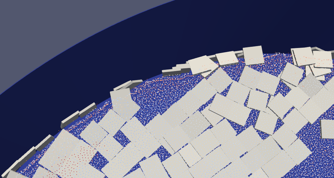
I want to implement mDBC because floating bodies in my case are falling between the boundary particles and the fluid particles (see screenshot) so I want to avoid this gap. Otherwise, is there any other solutions to avoid this problem ?
Best regards,
Clement B.
Debug Trace
| Notice |
rich is deprecated. Use FormatService::renderHtml($content, Formats\RichFormat::FORMAT_KEY) instead.

#0 [internal function]: gdn_ErrorHandler(16384, 'rich is depreca...', '/var/www/forums...', 950, Array)
#1 /var/www/forums-dual-sphysics-org/library/core/functions.general.php(950): trigger_error('rich is depreca...', 16384)
#2 /var/www/forums-dual-sphysics-org/library/core/class.format.php(1729): deprecated('rich', 'FormatService::...')
#3 /var/www/forums-dual-sphysics-org/library/core/class.format.php(1479): Gdn_Format::rich('[{"insert":"Hel...')
#4 /var/www/forums-dual-sphysics-org/applications/vanilla/controllers/class.discussioncontroller.php(197): Gdn_Format::to('[{"insert":"Hel...', 'Rich')
#5 /var/www/forums-dual-sphysics-org/applications/vanilla/controllers/class.discussioncontroller.php(402): DiscussionController->index(2159, 'x', 'p1')
#6 /var/www/forums-dual-sphysics-org/library/core/class.dispatcher.php(862): DiscussionController->comment('4730')
#7 /var/www/forums-dual-sphysics-org/library/core/class.dispatcher.php(279): Gdn_Dispatcher->dispatchController(Object(Gdn_Request), Array)
#8 /var/www/forums-dual-sphysics-org/index.php(29): Gdn_Dispatcher->dispatch()
#9 {main} |
| Notice |
rich is deprecated. Use FormatService::renderHtml($content, Formats\RichFormat::FORMAT_KEY) instead.

#0 [internal function]: gdn_ErrorHandler(16384, 'rich is depreca...', '/var/www/forums...', 950, Array)
#1 /var/www/forums-dual-sphysics-org/library/core/functions.general.php(950): trigger_error('rich is depreca...', 16384)
#2 /var/www/forums-dual-sphysics-org/library/core/class.format.php(1729): deprecated('rich', 'FormatService::...')
#3 /var/www/forums-dual-sphysics-org/library/core/class.format.php(1479): Gdn_Format::rich('[{"insert":"Hel...')
#4 /var/www/forums-dual-sphysics-org/applications/vanilla/views/discussion/helper_functions.php(24): Gdn_Format::to('[{"insert":"Hel...', 'Rich')
#5 /var/www/forums-dual-sphysics-org/applications/vanilla/views/discussion/discussion.php(89): formatBody(Object(stdClass))
#6 /var/www/forums-dual-sphysics-org/applications/vanilla/views/discussion/index.php(31): include('/var/www/forums...')
#7 /var/www/forums-dual-sphysics-org/library/core/class.controller.php(778): include('/var/www/forums...')
#8 /var/www/forums-dual-sphysics-org/library/core/class.controller.php(1382): Gdn_Controller->fetchView('', false, false)
#9 /var/www/forums-dual-sphysics-org/library/core/class.pluggable.php(217): Gdn_Controller->xRender()
#10 /var/www/forums-dual-sphysics-org/applications/vanilla/controllers/class.discussioncontroller.php(310): Gdn_Pluggable->__call('render', Array)
#11 /var/www/forums-dual-sphysics-org/applications/vanilla/controllers/class.discussioncontroller.php(402): DiscussionController->index(2159, 'x', 'p1')
#12 /var/www/forums-dual-sphysics-org/library/core/class.dispatcher.php(862): DiscussionController->comment('4730')
#13 /var/www/forums-dual-sphysics-org/library/core/class.dispatcher.php(279): Gdn_Dispatcher->dispatchController(Object(Gdn_Request), Array)
#14 /var/www/forums-dual-sphysics-org/index.php(29): Gdn_Dispatcher->dispatch()
#15 {main} |
| Notice |
rich is deprecated. Use FormatService::renderHtml($content, Formats\RichFormat::FORMAT_KEY) instead.

#0 [internal function]: gdn_ErrorHandler(16384, 'rich is depreca...', '/var/www/forums...', 950, Array)
#1 /var/www/forums-dual-sphysics-org/library/core/functions.general.php(950): trigger_error('rich is depreca...', 16384)
#2 /var/www/forums-dual-sphysics-org/library/core/class.format.php(1729): deprecated('rich', 'FormatService::...')
#3 /var/www/forums-dual-sphysics-org/library/core/class.format.php(1479): Gdn_Format::rich('[{"insert":"Hav...')
#4 /var/www/forums-dual-sphysics-org/applications/vanilla/views/discussion/helper_functions.php(24): Gdn_Format::to('[{"insert":"Hav...', 'Rich')
#5 /var/www/forums-dual-sphysics-org/applications/vanilla/views/discussion/helper_functions.php(170): formatBody(Object(stdClass))
#6 /var/www/forums-dual-sphysics-org/applications/vanilla/views/discussion/comments.php(19): writeComment(Object(stdClass), Object(DiscussionController), Object(Gdn_Session), 1)
#7 /var/www/forums-dual-sphysics-org/applications/vanilla/views/discussion/index.php(53): include('/var/www/forums...')
#8 /var/www/forums-dual-sphysics-org/library/core/class.controller.php(778): include('/var/www/forums...')
#9 /var/www/forums-dual-sphysics-org/library/core/class.controller.php(1382): Gdn_Controller->fetchView('', false, false)
#10 /var/www/forums-dual-sphysics-org/library/core/class.pluggable.php(217): Gdn_Controller->xRender()
#11 /var/www/forums-dual-sphysics-org/applications/vanilla/controllers/class.discussioncontroller.php(310): Gdn_Pluggable->__call('render', Array)
#12 /var/www/forums-dual-sphysics-org/applications/vanilla/controllers/class.discussioncontroller.php(402): DiscussionController->index(2159, 'x', 'p1')
#13 /var/www/forums-dual-sphysics-org/library/core/class.dispatcher.php(862): DiscussionController->comment('4730')
#14 /var/www/forums-dual-sphysics-org/library/core/class.dispatcher.php(279): Gdn_Dispatcher->dispatchController(Object(Gdn_Request), Array)
#15 /var/www/forums-dual-sphysics-org/index.php(29): Gdn_Dispatcher->dispatch()
#16 {main} |
| Notice |
rich is deprecated. Use FormatService::renderHtml($content, Formats\RichFormat::FORMAT_KEY) instead.

#0 [internal function]: gdn_ErrorHandler(16384, 'rich is depreca...', '/var/www/forums...', 950, Array)
#1 /var/www/forums-dual-sphysics-org/library/core/functions.general.php(950): trigger_error('rich is depreca...', 16384)
#2 /var/www/forums-dual-sphysics-org/library/core/class.format.php(1729): deprecated('rich', 'FormatService::...')
#3 /var/www/forums-dual-sphysics-org/library/core/class.format.php(1479): Gdn_Format::rich('[{"insert":"Tha...')
#4 /var/www/forums-dual-sphysics-org/applications/vanilla/views/discussion/helper_functions.php(24): Gdn_Format::to('[{"insert":"Tha...', 'Rich')
#5 /var/www/forums-dual-sphysics-org/applications/vanilla/views/discussion/helper_functions.php(170): formatBody(Object(stdClass))
#6 /var/www/forums-dual-sphysics-org/applications/vanilla/views/discussion/comments.php(19): writeComment(Object(stdClass), Object(DiscussionController), Object(Gdn_Session), 2)
#7 /var/www/forums-dual-sphysics-org/applications/vanilla/views/discussion/index.php(53): include('/var/www/forums...')
#8 /var/www/forums-dual-sphysics-org/library/core/class.controller.php(778): include('/var/www/forums...')
#9 /var/www/forums-dual-sphysics-org/library/core/class.controller.php(1382): Gdn_Controller->fetchView('', false, false)
#10 /var/www/forums-dual-sphysics-org/library/core/class.pluggable.php(217): Gdn_Controller->xRender()
#11 /var/www/forums-dual-sphysics-org/applications/vanilla/controllers/class.discussioncontroller.php(310): Gdn_Pluggable->__call('render', Array)
#12 /var/www/forums-dual-sphysics-org/applications/vanilla/controllers/class.discussioncontroller.php(402): DiscussionController->index(2159, 'x', 'p1')
#13 /var/www/forums-dual-sphysics-org/library/core/class.dispatcher.php(862): DiscussionController->comment('4730')
#14 /var/www/forums-dual-sphysics-org/library/core/class.dispatcher.php(279): Gdn_Dispatcher->dispatchController(Object(Gdn_Request), Array)
#15 /var/www/forums-dual-sphysics-org/index.php(29): Gdn_Dispatcher->dispatch()
#16 {main} |
| Notice |
rich is deprecated. Use FormatService::renderHtml($content, Formats\RichFormat::FORMAT_KEY) instead.

#0 [internal function]: gdn_ErrorHandler(16384, 'rich is depreca...', '/var/www/forums...', 950, Array)
#1 /var/www/forums-dual-sphysics-org/library/core/functions.general.php(950): trigger_error('rich is depreca...', 16384)
#2 /var/www/forums-dual-sphysics-org/library/core/class.format.php(1729): deprecated('rich', 'FormatService::...')
#3 /var/www/forums-dual-sphysics-org/library/core/class.format.php(1479): Gdn_Format::rich('[{"insert":{"em...')
#4 /var/www/forums-dual-sphysics-org/applications/vanilla/views/discussion/helper_functions.php(24): Gdn_Format::to('[{"insert":{"em...', 'Rich')
#5 /var/www/forums-dual-sphysics-org/applications/vanilla/views/discussion/helper_functions.php(170): formatBody(Object(stdClass))
#6 /var/www/forums-dual-sphysics-org/applications/vanilla/views/discussion/comments.php(19): writeComment(Object(stdClass), Object(DiscussionController), Object(Gdn_Session), 3)
#7 /var/www/forums-dual-sphysics-org/applications/vanilla/views/discussion/index.php(53): include('/var/www/forums...')
#8 /var/www/forums-dual-sphysics-org/library/core/class.controller.php(778): include('/var/www/forums...')
#9 /var/www/forums-dual-sphysics-org/library/core/class.controller.php(1382): Gdn_Controller->fetchView('', false, false)
#10 /var/www/forums-dual-sphysics-org/library/core/class.pluggable.php(217): Gdn_Controller->xRender()
#11 /var/www/forums-dual-sphysics-org/applications/vanilla/controllers/class.discussioncontroller.php(310): Gdn_Pluggable->__call('render', Array)
#12 /var/www/forums-dual-sphysics-org/applications/vanilla/controllers/class.discussioncontroller.php(402): DiscussionController->index(2159, 'x', 'p1')
#13 /var/www/forums-dual-sphysics-org/library/core/class.dispatcher.php(862): DiscussionController->comment('4730')
#14 /var/www/forums-dual-sphysics-org/library/core/class.dispatcher.php(279): Gdn_Dispatcher->dispatchController(Object(Gdn_Request), Array)
#15 /var/www/forums-dual-sphysics-org/index.php(29): Gdn_Dispatcher->dispatch()
#16 {main} |
| Notice |
rich is deprecated. Use FormatService::renderHtml($content, Formats\RichFormat::FORMAT_KEY) instead.

#0 [internal function]: gdn_ErrorHandler(16384, 'rich is depreca...', '/var/www/forums...', 950, Array)
#1 /var/www/forums-dual-sphysics-org/library/core/functions.general.php(950): trigger_error('rich is depreca...', 16384)
#2 /var/www/forums-dual-sphysics-org/library/core/class.format.php(1729): deprecated('rich', 'FormatService::...')
#3 /var/www/forums-dual-sphysics-org/library/core/class.format.php(1479): Gdn_Format::rich('[{"insert":"Hel...')
#4 /var/www/forums-dual-sphysics-org/applications/vanilla/views/discussion/helper_functions.php(24): Gdn_Format::to('[{"insert":"Hel...', 'Rich')
#5 /var/www/forums-dual-sphysics-org/applications/vanilla/views/discussion/helper_functions.php(170): formatBody(Object(stdClass))
#6 /var/www/forums-dual-sphysics-org/applications/vanilla/views/discussion/comments.php(19): writeComment(Object(stdClass), Object(DiscussionController), Object(Gdn_Session), 4)
#7 /var/www/forums-dual-sphysics-org/applications/vanilla/views/discussion/index.php(53): include('/var/www/forums...')
#8 /var/www/forums-dual-sphysics-org/library/core/class.controller.php(778): include('/var/www/forums...')
#9 /var/www/forums-dual-sphysics-org/library/core/class.controller.php(1382): Gdn_Controller->fetchView('', false, false)
#10 /var/www/forums-dual-sphysics-org/library/core/class.pluggable.php(217): Gdn_Controller->xRender()
#11 /var/www/forums-dual-sphysics-org/applications/vanilla/controllers/class.discussioncontroller.php(310): Gdn_Pluggable->__call('render', Array)
#12 /var/www/forums-dual-sphysics-org/applications/vanilla/controllers/class.discussioncontroller.php(402): DiscussionController->index(2159, 'x', 'p1')
#13 /var/www/forums-dual-sphysics-org/library/core/class.dispatcher.php(862): DiscussionController->comment('4730')
#14 /var/www/forums-dual-sphysics-org/library/core/class.dispatcher.php(279): Gdn_Dispatcher->dispatchController(Object(Gdn_Request), Array)
#15 /var/www/forums-dual-sphysics-org/index.php(29): Gdn_Dispatcher->dispatch()
#16 {main} |
| Notice |
rich is deprecated. Use FormatService::renderHtml($content, Formats\RichFormat::FORMAT_KEY) instead.

#0 [internal function]: gdn_ErrorHandler(16384, 'rich is depreca...', '/var/www/forums...', 950, Array)
#1 /var/www/forums-dual-sphysics-org/library/core/functions.general.php(950): trigger_error('rich is depreca...', 16384)
#2 /var/www/forums-dual-sphysics-org/library/core/class.format.php(1729): deprecated('rich', 'FormatService::...')
#3 /var/www/forums-dual-sphysics-org/library/core/class.format.php(1479): Gdn_Format::rich('[{"insert":{"em...')
#4 /var/www/forums-dual-sphysics-org/applications/vanilla/views/discussion/helper_functions.php(24): Gdn_Format::to('[{"insert":{"em...', 'Rich')
#5 /var/www/forums-dual-sphysics-org/applications/vanilla/views/discussion/helper_functions.php(170): formatBody(Object(stdClass))
#6 /var/www/forums-dual-sphysics-org/applications/vanilla/views/discussion/comments.php(19): writeComment(Object(stdClass), Object(DiscussionController), Object(Gdn_Session), 5)
#7 /var/www/forums-dual-sphysics-org/applications/vanilla/views/discussion/index.php(53): include('/var/www/forums...')
#8 /var/www/forums-dual-sphysics-org/library/core/class.controller.php(778): include('/var/www/forums...')
#9 /var/www/forums-dual-sphysics-org/library/core/class.controller.php(1382): Gdn_Controller->fetchView('', false, false)
#10 /var/www/forums-dual-sphysics-org/library/core/class.pluggable.php(217): Gdn_Controller->xRender()
#11 /var/www/forums-dual-sphysics-org/applications/vanilla/controllers/class.discussioncontroller.php(310): Gdn_Pluggable->__call('render', Array)
#12 /var/www/forums-dual-sphysics-org/applications/vanilla/controllers/class.discussioncontroller.php(402): DiscussionController->index(2159, 'x', 'p1')
#13 /var/www/forums-dual-sphysics-org/library/core/class.dispatcher.php(862): DiscussionController->comment('4730')
#14 /var/www/forums-dual-sphysics-org/library/core/class.dispatcher.php(279): Gdn_Dispatcher->dispatchController(Object(Gdn_Request), Array)
#15 /var/www/forums-dual-sphysics-org/index.php(29): Gdn_Dispatcher->dispatch()
#16 {main} |
| Notice |
rich is deprecated. Use FormatService::renderHtml($content, Formats\RichFormat::FORMAT_KEY) instead.

#0 [internal function]: gdn_ErrorHandler(16384, 'rich is depreca...', '/var/www/forums...', 950, Array)
#1 /var/www/forums-dual-sphysics-org/library/core/functions.general.php(950): trigger_error('rich is depreca...', 16384)
#2 /var/www/forums-dual-sphysics-org/library/core/class.format.php(1729): deprecated('rich', 'FormatService::...')
#3 /var/www/forums-dual-sphysics-org/library/core/class.format.php(1479): Gdn_Format::rich('[{"insert":"Rig...')
#4 /var/www/forums-dual-sphysics-org/applications/vanilla/views/discussion/helper_functions.php(24): Gdn_Format::to('[{"insert":"Rig...', 'Rich')
#5 /var/www/forums-dual-sphysics-org/applications/vanilla/views/discussion/helper_functions.php(170): formatBody(Object(stdClass))
#6 /var/www/forums-dual-sphysics-org/applications/vanilla/views/discussion/comments.php(19): writeComment(Object(stdClass), Object(DiscussionController), Object(Gdn_Session), 6)
#7 /var/www/forums-dual-sphysics-org/applications/vanilla/views/discussion/index.php(53): include('/var/www/forums...')
#8 /var/www/forums-dual-sphysics-org/library/core/class.controller.php(778): include('/var/www/forums...')
#9 /var/www/forums-dual-sphysics-org/library/core/class.controller.php(1382): Gdn_Controller->fetchView('', false, false)
#10 /var/www/forums-dual-sphysics-org/library/core/class.pluggable.php(217): Gdn_Controller->xRender()
#11 /var/www/forums-dual-sphysics-org/applications/vanilla/controllers/class.discussioncontroller.php(310): Gdn_Pluggable->__call('render', Array)
#12 /var/www/forums-dual-sphysics-org/applications/vanilla/controllers/class.discussioncontroller.php(402): DiscussionController->index(2159, 'x', 'p1')
#13 /var/www/forums-dual-sphysics-org/library/core/class.dispatcher.php(862): DiscussionController->comment('4730')
#14 /var/www/forums-dual-sphysics-org/library/core/class.dispatcher.php(279): Gdn_Dispatcher->dispatchController(Object(Gdn_Request), Array)
#15 /var/www/forums-dual-sphysics-org/index.php(29): Gdn_Dispatcher->dispatch()
#16 {main} |
| Notice |
rich is deprecated. Use FormatService::renderHtml($content, Formats\RichFormat::FORMAT_KEY) instead.

#0 [internal function]: gdn_ErrorHandler(16384, 'rich is depreca...', '/var/www/forums...', 950, Array)
#1 /var/www/forums-dual-sphysics-org/library/core/functions.general.php(950): trigger_error('rich is depreca...', 16384)
#2 /var/www/forums-dual-sphysics-org/library/core/class.format.php(1729): deprecated('rich', 'FormatService::...')
#3 /var/www/forums-dual-sphysics-org/library/core/class.format.php(1479): Gdn_Format::rich('[{"insert":"Hey...')
#4 /var/www/forums-dual-sphysics-org/applications/vanilla/views/discussion/helper_functions.php(24): Gdn_Format::to('[{"insert":"Hey...', 'Rich')
#5 /var/www/forums-dual-sphysics-org/applications/vanilla/views/discussion/helper_functions.php(170): formatBody(Object(stdClass))
#6 /var/www/forums-dual-sphysics-org/applications/vanilla/views/discussion/comments.php(19): writeComment(Object(stdClass), Object(DiscussionController), Object(Gdn_Session), 7)
#7 /var/www/forums-dual-sphysics-org/applications/vanilla/views/discussion/index.php(53): include('/var/www/forums...')
#8 /var/www/forums-dual-sphysics-org/library/core/class.controller.php(778): include('/var/www/forums...')
#9 /var/www/forums-dual-sphysics-org/library/core/class.controller.php(1382): Gdn_Controller->fetchView('', false, false)
#10 /var/www/forums-dual-sphysics-org/library/core/class.pluggable.php(217): Gdn_Controller->xRender()
#11 /var/www/forums-dual-sphysics-org/applications/vanilla/controllers/class.discussioncontroller.php(310): Gdn_Pluggable->__call('render', Array)
#12 /var/www/forums-dual-sphysics-org/applications/vanilla/controllers/class.discussioncontroller.php(402): DiscussionController->index(2159, 'x', 'p1')
#13 /var/www/forums-dual-sphysics-org/library/core/class.dispatcher.php(862): DiscussionController->comment('4730')
#14 /var/www/forums-dual-sphysics-org/library/core/class.dispatcher.php(279): Gdn_Dispatcher->dispatchController(Object(Gdn_Request), Array)
#15 /var/www/forums-dual-sphysics-org/index.php(29): Gdn_Dispatcher->dispatch()
#16 {main} |
| Notice |
rich is deprecated. Use FormatService::renderHtml($content, Formats\RichFormat::FORMAT_KEY) instead.

#0 [internal function]: gdn_ErrorHandler(16384, 'rich is depreca...', '/var/www/forums...', 950, Array)
#1 /var/www/forums-dual-sphysics-org/library/core/functions.general.php(950): trigger_error('rich is depreca...', 16384)
#2 /var/www/forums-dual-sphysics-org/library/core/class.format.php(1729): deprecated('rich', 'FormatService::...')
#3 /var/www/forums-dual-sphysics-org/library/core/class.format.php(1479): Gdn_Format::rich('[{"insert":"Man...')
#4 /var/www/forums-dual-sphysics-org/applications/vanilla/views/discussion/helper_functions.php(24): Gdn_Format::to('[{"insert":"Man...', 'Rich')
#5 /var/www/forums-dual-sphysics-org/applications/vanilla/views/discussion/helper_functions.php(170): formatBody(Object(stdClass))
#6 /var/www/forums-dual-sphysics-org/applications/vanilla/views/discussion/comments.php(19): writeComment(Object(stdClass), Object(DiscussionController), Object(Gdn_Session), 8)
#7 /var/www/forums-dual-sphysics-org/applications/vanilla/views/discussion/index.php(53): include('/var/www/forums...')
#8 /var/www/forums-dual-sphysics-org/library/core/class.controller.php(778): include('/var/www/forums...')
#9 /var/www/forums-dual-sphysics-org/library/core/class.controller.php(1382): Gdn_Controller->fetchView('', false, false)
#10 /var/www/forums-dual-sphysics-org/library/core/class.pluggable.php(217): Gdn_Controller->xRender()
#11 /var/www/forums-dual-sphysics-org/applications/vanilla/controllers/class.discussioncontroller.php(310): Gdn_Pluggable->__call('render', Array)
#12 /var/www/forums-dual-sphysics-org/applications/vanilla/controllers/class.discussioncontroller.php(402): DiscussionController->index(2159, 'x', 'p1')
#13 /var/www/forums-dual-sphysics-org/library/core/class.dispatcher.php(862): DiscussionController->comment('4730')
#14 /var/www/forums-dual-sphysics-org/library/core/class.dispatcher.php(279): Gdn_Dispatcher->dispatchController(Object(Gdn_Request), Array)
#15 /var/www/forums-dual-sphysics-org/index.php(29): Gdn_Dispatcher->dispatch()
#16 {main} |
| Notice |
rich is deprecated. Use FormatService::renderHtml($content, Formats\RichFormat::FORMAT_KEY) instead.

#0 [internal function]: gdn_ErrorHandler(16384, 'rich is depreca...', '/var/www/forums...', 950, Array)
#1 /var/www/forums-dual-sphysics-org/library/core/functions.general.php(950): trigger_error('rich is depreca...', 16384)
#2 /var/www/forums-dual-sphysics-org/library/core/class.format.php(1729): deprecated('rich', 'FormatService::...')
#3 /var/www/forums-dual-sphysics-org/library/core/class.format.php(1479): Gdn_Format::rich('[{"insert":"Hi ...')
#4 /var/www/forums-dual-sphysics-org/applications/vanilla/views/discussion/helper_functions.php(24): Gdn_Format::to('[{"insert":"Hi ...', 'Rich')
#5 /var/www/forums-dual-sphysics-org/applications/vanilla/views/discussion/helper_functions.php(170): formatBody(Object(stdClass))
#6 /var/www/forums-dual-sphysics-org/applications/vanilla/views/discussion/comments.php(19): writeComment(Object(stdClass), Object(DiscussionController), Object(Gdn_Session), 9)
#7 /var/www/forums-dual-sphysics-org/applications/vanilla/views/discussion/index.php(53): include('/var/www/forums...')
#8 /var/www/forums-dual-sphysics-org/library/core/class.controller.php(778): include('/var/www/forums...')
#9 /var/www/forums-dual-sphysics-org/library/core/class.controller.php(1382): Gdn_Controller->fetchView('', false, false)
#10 /var/www/forums-dual-sphysics-org/library/core/class.pluggable.php(217): Gdn_Controller->xRender()
#11 /var/www/forums-dual-sphysics-org/applications/vanilla/controllers/class.discussioncontroller.php(310): Gdn_Pluggable->__call('render', Array)
#12 /var/www/forums-dual-sphysics-org/applications/vanilla/controllers/class.discussioncontroller.php(402): DiscussionController->index(2159, 'x', 'p1')
#13 /var/www/forums-dual-sphysics-org/library/core/class.dispatcher.php(862): DiscussionController->comment('4730')
#14 /var/www/forums-dual-sphysics-org/library/core/class.dispatcher.php(279): Gdn_Dispatcher->dispatchController(Object(Gdn_Request), Array)
#15 /var/www/forums-dual-sphysics-org/index.php(29): Gdn_Dispatcher->dispatch()
#16 {main} |
Comments
Have you tried starting from one box and getting one stl to work? Then scaling up slowly, perhaps that could weed out some issues.
In my experience mDBC and stl can be combined, but it can be a bit difficult, so have to be patient and always plot the normals in Paraview etc.
Kind regards
Thanks for your answer, as suggested I will try with one box in stl and see how I can implement that.
However my final geometry contain a curve, do you think implementing curved boundary particles layers with their normals is possible ?
Best regards
Hello, yes, but you should play around with the smoothing length parameter in normal generations section and increase it from 2.0 to something higher.
Kind regards
Hello again,
The normals are working! However, I can't use the "layers vdp" command in the "drawfilestl" section so I am not able to create the boundary particles layers, how can I implement that ?
Thanks in advance,
Regards
Clement
This is unfortunately an area where the options in DualSPHysics are limited. Your best bet is to draw the stl faces directly and have a few different version which all have been shrunk approximately.
Let me know if you find a better way for layers, of course you can always use fillbox to fill the stl.
Kind regards
Right now your best option can be to use two STL files:
1) one with the actual geometry that you will use to define the Case_hpd_Actual.vtk that will compute normals
2) second one that can be created with faces at half dp or less inside the previous one (I think you can use SOLIDIFY transformation of Blender to do that) and this second one will be use to create the particles
So you have to check if there are normal vectores between the particles generated with 2) that starts from the particles and ends at the position defined in 1)
Regards
Alex
Hey @Alex ,is your last answer here still the most recent solution to this problem? I'm having the same problem implementing mDBC into my testcase at the moment
Managed to solve it by the way, basically the same way Alex described it. You have to create two stl's for each of your boundatries where you scale one of them down a little bit and then follow the mDBC example 04-dambreak
Hi @Zwulch,
I would like to ask, how you solved the additional layers of particles manually constructed in the 04-dambreak case? I tried the trick with two STL. I'm able to obtain normals, but only one layer of boundary particles.
I start with the import of smaller stl and reset the draw as in case of 04-dambreak example:
Then I import the stl with original size:
Then add some fluid, etc (simplified as much as possible, just to test this)..
And then I just call the hdp file to generate normals.
Normals are ok. Case__Actual.vtk and CaseDamBreak3D_hdp_Actual.vtk seems to be also fine (the gap is at it should be). But additional layers of boundary particles are missing. I thought that is done automatically as in DBC case, as the structure of boundary particles should be the same.
Could I ask you for a small hint?